Recently, Professor Li Tao and Academician Zhu Shining, along with their research team from the School of Engineering and Applied Sciences, published a research paper titled “Manipulating the Non-Hermitian Skin Effect in Optical Ring Resonators” on Physical Review B(Phys. Rev. B 107, 165401(2023))https://journals.aps.org/prb/abstract/10.1103/PhysRevB.107.165401.
The abstract of the paper is as following:
Non-Hermitian skin effects (NHSEs) enrich the traditional band theories and give rise to unique non-Hermitian topological properties. Here, the research team reveals a different type of NHSE, termed the V-shaped NHSE, and explore an on-chip optical ring resonator platform to demonstrate the NHSE in telecommunication wavelength. By tuning the hopping and loss modulation, the research team works out a phase diagram that reveals the phase transition of the NHSE. Besides the conventional NHSE and the frequency-dependent bipolar NHSE, another type of NHSE is observed featuring an interesting V shape in its special skin states distribution. The researchers further design a silicon ring resonator array with loss-assisted antiresonating coupling as the link resonators to demonstrate the nontrivial NHSE. The simulations show that one can tune the number of states piled up at different ends by switching the NHSE from conventional, bipolar to V-shaped types continuously. The team’s work enriches the NHSE phase transitions and implies potential in on-chip light modulation by the NHSE.

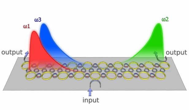
1. Schematic diagram of multiple V-shaped non-Ermy skinning effects in resonant ring arrays.

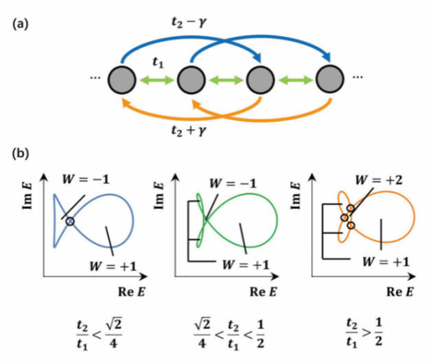
2. Schematic diagram of the single-atom chain model (a) A one-dimensional single-atom chain with asymmetric sub-nearest-neighbor coupling. (b) Three different non-Euclidean phases and their boundaries, from left to right, bipolar, V-shaped, and vanilla skinning effects.

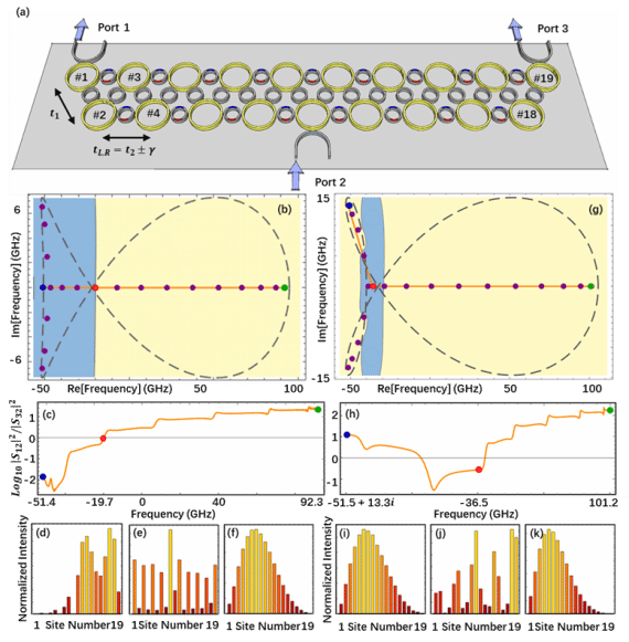
3. Schematic diagram of the resonant ring array realizing the skinning effect (a) Schematic diagram of the ring array system. (b,g) The complex frequency plane response of the system, blue and yellow corresponding to the skinning states of the left and right end pile-ups, respectively. (c,h) The transmittance ratio functions of ports 1 and 3 corresponding to the orange paths in Fig. (b,g). (d~f,i~k) The normalized light field energy distribution corresponding to the blue, red and green points in Fig. (b~c,g~h).
Translator: Shao Yihang
Editors: Guo Ankang, Shao Yihang
